The Dose Junction Issue Associated with Photon Beams for Large Volume Radiation Therapy and the Sensitivity to Set-up Error
Fred Cao, Sheryl Harrop, Nancy Cooper, Peter Steiner and Anand Karvat
Fred Cao1*, Sheryl Harrop1, Nancy Cooper2, Peter Steiner2 and Anand Karvat2
1Department of Medical Physics, Fraser Valley Centre, FVC_BCCA Surrey, Canada
2Department of Radiation Oncology, BC Cancer Agency, FVC_BCCA Surrey, British Columbia, Canada
- *Corresponding Author:
- Fred Cao
Department of Medical Physics
Fraser Valley Centre, 13750 96th Avenue
FVC_BCCA Surrey, BC, Canada
Tel: 604-930-4055
Fax: 604-930-4042
E-mail: fcao@bccancer.bc.ca
Received date: 16 June 2017; Accepted date: 14 July 2017; Published date: 20 July 2017
Citation: Cao F, Harrop S, Cooper N, Steiner P, Karvat A (2017) The Dose Junction Issue Associated with Photon Beams for Large Volume Radiation Therapy and the Sensitivity to Set-up Error. J Med Phy Appl Sci. Vol.2 No.2:8.
Abstract
Purpose: Radiation therapy involving large treatment volumes requires multiple radiation fields having different isocenters; dosing across field junctions and sensitivity to setup error must be addressed. Some published papers presume that using IMRT techniques alone will ensure treatment is not sensitive to setup error. We compared Jagged-Junction-IMRT (JJ-IMRT), Non-Jagged-Junction- IMRT (NJJ-IMRT) and VMAT to demonstrate how these different techniques address the dose junction issue and how this made each technique more or less sensitive to setup error.
Method: A JJ-IMRT plan was developed and used to treat a patient using 6-MV photons and a 120-leaf multi-leaf collimator. NJJ-IMRT and VMAT plans were retrospectively developed with the same patient. Verification of the dose delivered to the cranio-spinal junction region for JJ-IMRT, NJJ-IMRT and VMAT were done through ion chamber and film measurements on a human-shaped wax phantom. For film measurements, each verification plan was delivered twice, with and without setup error in the longitudinal direction.
Results: The difference between measured dose with ion chamber and planned dose from the verification plans was 1.59% for JJ-IMRT, 1.35% for NJJ-IMRT and 1.68% for VMAT. The maximum difference in dose profiles between film measurements with and without setup error was less than 4% for JJ-IMRT, less than 6% for VMAT and about 10% for NJJ-IMRT.
Conclusion: IMRT and VMAT techniques alone will not make treatment plans insensitive to setup error. Ensuring that beam field edges are not all placed on the same line is the reason the plans are not sensitive to setup error.
Keywords
CSI; IMRT/VMAT; Field junction; Setup error
Introduction
Radiation therapy often requires the treatment of large volumes requiring multiple fields of radiation having different isocenters. Due to machine limitations, the maximum field size for Varian high energy linear accelerators is 40 × 40 cm at isocenter with a source-to-axis distance (SAD) of 100 cm. To deal with larger field sizes, radiation therapy requires the junction of multiple fields and care must be taken when aligning adjacent fields to avoid the formation of hot and cold spots. To attempt to about one field up against another field is not feasible due to different directions of beam divergences. The alternative is to overlap field edges in such a way as to be able to control the combined dose in the junction region. A number of approaches have been developed to deal with the dose junction issue with varying levels of success [1-11]. When aligning fields, one must also consider the possibility of set-up error; even a small setup error can lead to an unexpected increase or decrease in field overlap or mismatching resulting in unintentional high or low doses [12].
We have developed a novel IMRT technique called Jagged- Junction-IMRT (JJ-IMRT) that addresses the dose junction issues associated with multiple radiation fields [13]. The method was originally developed for cranio-spinal irradiation (CSI). JJ-IMRT for CSI uses a three-isocenter IMRT plan that handles the junction issues by intentionally overlapping adjacent fields, with a different field edge location for each field, and letting the optimization process smoothly blend the dose from these fields. The intentional ‘jagging’ of the field edges results in the junction being insensitive to set-up error [13].
Wang et al. [14] have also developed an IMRT method for CSI which they claim, when compared to the JJ-IMRT technique, further simplifies the planning process for CSI. Their IMRT technique, referred to here as Non-Jagged-Junction- IMRT (NJJ-IMRT) simplifies the steps required to manually set field widths and boundaries by allowing the optimization to freely open the field size as needed. As a result, all the fields open to their maximum size and all field edges from the same iso-center end on the same line. Because of this, we believe the NJJ-IMRT method becomes more sensitive to setup error.
Volumetric modulated arc therapy (VMAT) can also be used for large treatment fields that require beam matching and has been used for CSI. Due to the VMAT beam and collimator arrangements, most VMAT plans should not be sensitive to setup error [12,15].
In this paper, we will compare the three techniques, JJ-IMRT, NJJ-IMRT and VMAT, with a CSI case as the example, in terms of sensitivity to treatment setup error. We will demonstrate how the different techniques address the dose junction issue and how this makes each technique more or less sensitive to setup error.
Materials and Methods
Planning
A JJ-IMRT plan was developed and used to treat a patient using Varian Eclipse (Version 11.0.31) with 6-MV photons and a 120-leaf multi-leaf collimator. NJJ-IMRT and VMAT plans were retrospectively developed for the same patient data set.
The planning target volume (PTV) and organs at risk (OAR) contours were defined on a computed tomography (CT) image set. The PTV included the whole brain with a three millimetre margin and the spine from C1 to S3 with a five millimetre margin. The prescription dose was 36 Gy in 20 fractions to the PTV. The goal was to have 99% of the PTV covered by 95% of the prescribed dose. The planning objectives were kept the same for all three plans.
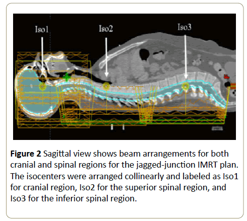
Plans covered the PTVs with the use of three isocenters. One isocenter (Iso1) was placed in the cranial PTV, and two isocenters (Iso2 and Iso3) were placed in the spinal PTV, with Iso2 located superior to Iso3. The three isocenters were collinear, and were placed near the patient’s midline. The same isocenters were used for the NJJ-IMRT and VMAT plans.
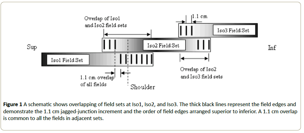
Planning for JJ-IMRT has been explained in detail elsewhere [13]. In brief, the JJ-IMRT plan was developed using 13 fields in total. The field set from Iso1 consisted of seven fields with gantry angles of 0°, 65°, 100°, 123°, 230°, 257° and 290°. Both field sets from Iso2 and Iso3 consisted of three beams with gantry angles 155°, 180° and 215°. Adjacent field sets were intentionally overlapped to treat a common region of the spine. The field edges were staggered in 1.1 cm steps so as to avoid an undesirable sharp dose gradient that resulted when a common jaw setting was used. Figure 1 shows a schematic diagram of the overlap regions. The net result was a 9.9 cm long overlap between the cranial and spinal field sets and a 5.5 cm overlap between the two spinal field sets. The field arrangements and isocenter placements are illustrated in Figure 2.
Figure 1: A schematic shows overlapping of field sets at Iso1, Iso2, and Iso3. The thick black lines represent the field edges and demonstrate the 1.1 cm jagged-junction increment and the order of field edges arranged superior to inferior. A 1.1 cm overlap is common to all the fields in adjacent sets.
The NJJ-IMRT plan was developed following the method of Wang et al. [14]. The same three isocenters were used as in the JJ-IMRT plan; the field sets for each isocenter were also the same. Unlike the JJ-IMRT plan, for NJJ-IMRT, the field size and shape were automatically set by the planning system. As a result, all seven fields of Iso1 have one of the jaws maximized to 20 cm, all three fields from Iso2 have both upper jaws, referred as Y1 and Y2 maximized to 20 cm, and all three fields from Iso3 have Y2 maximized to 20 cm.
For the VMAT plan, two full arcs were used for the head, Iso1, with collimator angles of 30° and 150°. For Iso2 and Iso3, each used a full arc with a collimator angle of 160° for Iso2 and 30° for Iso3. Jaw tracking was used.
Plan verification
Verification plans for JJ-IMRT, NJJ-IMRT and VMAT were delivered on a human shaped wax phantom, dubbed YuYu [13]. A Wellhofer ion chamber IC 10, placed in the coronal plane of YuYu at the craniospinal junction, was used for measurements. The ion chamber was then replaced with film and measurements were repeated.
For film measurements, each verification plan was delivered twice, one without setup error and one in which all fields from Iso2 had been shifted superiorly by 3 mm to simulate a setup error in the longitudinal direction. Two gafchromic EBT3 films, the bottom film (B-film) and top film (T-film), were placed in the coronal plane of YuYu at the craniospinal junction. Both films were in place for the Iso1 field irradiation. The T-film was then removed and replaced with a dummy film and the B-film was irradiated with the Iso2 fields. The B-film was then removed and represents the dose received across the craniospinal junction without setup error. The T-film was put back in place, along with a dummy film replacing the B-film. The T-film was irradiated with the Iso2 fields that had been now shifted superiorly 3 mm. The T-film represents the dose received across the craniospinal junction with a 3 mm setup error in the longitudinal direction.
The films were scanned using an Epson Expression 10000 XL scanner after been irradiated for approximately 36 hours. The profile of each film was obtained with Image J with Red channel only. The optical density was converted to dose using conversion calibration curves obtained with irradiated film at machine calibration point with SAD 100 cm, 10 × 10 cm2 field size and irradiated doses of 75, 100, 150, 175, 200 and 250 cGy at film depth.
Results
The difference between the measured dose with ion chamber and planned dose in the craniospinal junction from the verification plans was 1.59% for JJ-IMRT; 1.35% for NJJIMRT; and 1.68% for VMAT (Table 1).
| Plan type | % Dose Difference | |
|---|---|---|
| Without setup error | With setup error | |
| JJ-IMRT | 1.59 | < 4 |
| NJJ-IMRT | 1.35 | < 6 |
| VMAT | 1.68 | > 10 |
Table 1: The percentage difference between measured dose and planned dose at the craniospinal junction for Jagged- Junction-IMRT (JJ-IMRT), Non-Jagged-Junction-IMRT (NJJIMRT) and volumetric modulated arc therapy (VMAT) plans, with and without a 3 mm longitudinal setup error.
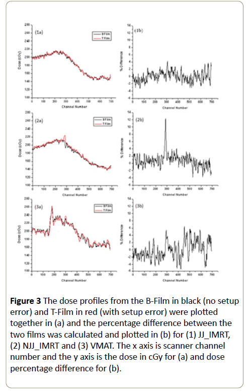
The dose profiles from the B-Film (no setup error) and TFilm (setup error) were plotted together and the percentage difference between the two films was also calculated and plotted (Figure 3).
Figure 3: The dose profiles from the B-Film in black (no setup error) and T-Film in red (with setup error) were plotted together in (a) and the percentage difference between the two films was calculated and plotted in (b) for (1) JJ_IMRT, (2) NJJ_IMRT and (3) VMAT. The x axis is scanner channel number and the y axis is the dose in cGy for (a) and dose percentage difference for (b).
For both the JJ_IMRT plans, the maximum difference between the B-Film and T-Film dose profiles was less than 4%. For VMAT plan, the percentage differences were less than 6%. For NJJ-IMRT plan, the percentage difference showed a more than 10% peak at the location of the junction edge (Table 1).
Table 1 The percentage difference between measured dose and planned dose at the craniospinal junction for Jagged- Junction-IMRT (JJ-IMRT), Non-Jagged-Junction-IMRT (NJJIMRT) and volumetric modulated arc therapy (VMAT) plans, with and without a 3 mm longitudinal setup error.
Discussion
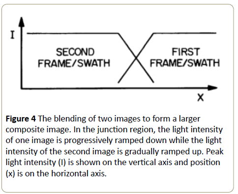
The dose junction issue associated with large treatment volumes is very similar to the problem of creating a large image that is beyond the capacity of the imaging device. The best way to create a seamless junction between adjacent frames is to have the image frames joined together not in an abutting relationship but in an overlapping relationship to form a junction region. Within this region the medium is doubly exposed but in such a way that the images are blended: the light intensity of the first image frame is progressively ramped down while the light intensity of the second image is progressively ramped up (Figure 4). This allows the formation of a composite image with a smooth junction between the two images [16]. This also allows the joining to be less sensitive to any setup error as a small shift of one of the images will result in only a portion of that image’s light intensity contributing to the error. Setup error in the case where images are abutted would result in either an area of no image or an area of two full image exposures.
Figure 4: The blending of two images to form a larger composite image. In the junction region, the light intensity of one image is progressively ramped down while the light intensity of the second image is gradually ramped up. Peak light intensity (I) is shown on the vertical axis and position (x) is on the horizontal axis.
In radiation therapy, the dose densities of the individual radiation fields cannot be linearly changed in the junction region to give a seamless blending as is possible with images. Instead, for JJ-IMRT plans, multiple overlapping radiation fields are used with field edges of a given isocenter being staggered so that the field edges do not end on the same line. In the CSI case, the fields from Iso1 and from Iso2 were overlapped over 10 cm with the field edges staggered in 1.1 cm steps. The selection of 1.1 cm steps is to make sure the staggered region is wider than at least one MLC. The staggered field edges form a “jagged” junction; the optimization process then smoothly blends the fluence contributions of each field to get the desired dose in the junction region. By handling the dose junction issue in a manner similar to that of blending images, JJ-IMRT becomes less sensitive to setup error. Patient set-up error and patient movement during treatment can contribute to small shifts in treatment fields; typical misalignment errors may vary between 0 mm and 3 mm. Our study demonstrated that a 3 mm setup error in the longitudinal direction resulted in less than a 4% dose difference in the craniospinal junction. This is due to the fact that an error shifting one isocenter will result in the dosing error from each field also being ‘jagged’ over the region of overlap, resulting in only a small dosing error at any given point. For serial organs such as the spinal cord the maximum dose received at any given point is of critical importance.
While the ‘jagging’ of field edges in JJ-IMRT would not be possible without the IMRT technique, IMRT alone, without ‘jagging’, would allow the field junctions to still be sensitive to treatment set-up error. If the multiple overlapping fields for a given isocenter all end on the same line, an error shifting one isocenter will result in the dosing error from each field occurring at the same junction edge, compounding the error. Our study demonstrated that for the NJJ-IMRT plan, in which field sizes are opened as needed by the optimization process with the result that all fields are opened to the maximum length set by the MLC and end on the same line; a 3 mm setup error in the longitudinal direction resulted in a more than 10% peak at the location of the junction edge. A point dose increase of more than 10% over the planned dose when treating the spinal cord should not be ignored. NJJ-IMRT may improve planning efficiency compared to JJ-IMRT but at the cost of increased sensitivity to setup error.
For VMAT, if the collimator orientations were all set to same angle, VMAT would have the same problem as NJJ-IMRT at the junction region. Instead, collimators were purposely set to different angles for the adjacent fields from each isocenter. As a result, the junction between Iso1 and Iso2 did not end up at the same line along the latitudinal direction. This makes the VMAT plan insensitive to a longitudinal setup error. VMAT may also uses jaw tracking which puts the edge of each field at a different location for the different gantry angles, again reducing the sensitivity of VMAT to setup error. Our study demonstrated that for VMAT, a 3 mm setup error in the longitudinal direction resulted in less than a 6% dose difference in dose profile obtained from the film measurement at the cranio-spinal junction. This was similar to JJ-IMRT.
Conclusion
IMRT and VMAT techniques alone will not make treatment plans insensitive to setup error. Ensuring that beam field edges are not all placed on the same line is the reason the plans are not sensitive to setup error. In this study, JJ-IMRT and VMAT were found to be relatively insensitive to setup error compared to NJJ-IMRT.
References
- Hawkins RB (2001) A simple method of radiation treatment of craniospinal fields with the patient supine. Int J RadiatOncolBiolPhys49:261–264.
- Parker W, Freeman CR (2006) A simple technique for craniospinal radiotherapy in the supine position. RadiotherOncol78:217-222.
- Thomadsen B, Mehta M, Howard S (2003) Craniospinal treatment with the patient supine. Med Dosim28:35–38.
- Tinkler SD, Lucraft HH (1995) Are moving junctions in craniospinal irradiation for medulloblastoma really necessary? Br J Radiol68:736–739.
- Tatcher M, Glicksman AS (1989) Field matching considerations in craniospinal irradiation. Int J Rad Onc Boil Phys17:865-869.
- Michalski JM, Klein EE, Gerber R (2002) Method to plan, administer, and verify supine craniospinal irradiation. J ApplClin Med Phys3:310–316.
- AthiyamanH, MayilvagananA, Singh D(2014) A simple planning technique of craniospinal irradiation in the eclipse treatment planning system. J Med Phys39:251–258.
- Followill D, Geis P, Boyer A (1997) Estimates of whole-body dose equivalent produced by beam intensity modulated conformal therapy. Int J RadiatOncolBiolPhys38:667-672.
- Kusters JMAM, Louwe RJW, Kollenberg PV,Janssens GO (2010) Optimal normal tissue sparing in craniospinal axis irradiation using IMRT with daily intrafractionally modulated junction(s). Int J RadiatOncolBiolPhys 81:1405-1414.
- Parker W, Filion E, Roberge D, Freeman CR (2007) Intensity-modulated radiotherapy for craniospinal irradiation: Target volume considerations, dose constraints, and competing risks. Int J RadiatOncolBiolPhys69:251–257.
- PanandikerPA, Ning H, Likhacheva A, Ullman K, Arora B, et al. (2007) Craniospinal irradiation with spinal IMRT to improve target homogeneity. Int J RadiatOncolBiolPhys 68:1402–1409.
- Fogliata A, Bergström S,Cafaro I, Clivio A, Cozzi L, et al. (2011)Cranio-spinal irradiation with volumetric modulated arc therapy: A multi-institutional treatment experience. Radiothera and Oncol 99:79–85.
- Cao F, RamaseshanR, Corns R, Harrop S, NuraneyN, et al. (2012)A three-isocentre jaggedjunction_IMRTapproach for craniospinal irradiation without beam edge matching for field junctions. Int J RadiatOncolBiolPhys84:648-654.
- Wang Z, Jiang W, Feng Y, Guo Y, Cong Z, et al. (2013)A simple approach of three-isocenter IMRT planning for craniospinal irradiation. RadiatiOncol 8:217.
- Li Q, Gu W, Mu J, Yin W, Gao M, et al. (2015) Collimator rotation in volumetric modulated arc therapy for craniospinal irradiation and the dose distribution in the beam junction region. RadiatiOncol10:235.
- CaoF, Hsu L, James G(2000) Method and apparatus for creating a composite image by the tiling of multiple image frames. United States Patent 6: 625.
Open Access Journals
- Aquaculture & Veterinary Science
- Chemistry & Chemical Sciences
- Clinical Sciences
- Engineering
- General Science
- Genetics & Molecular Biology
- Health Care & Nursing
- Immunology & Microbiology
- Materials Science
- Mathematics & Physics
- Medical Sciences
- Neurology & Psychiatry
- Oncology & Cancer Science
- Pharmaceutical Sciences


