A Novel Fluence Modified Base Plan IMRT for Second-irradiation Planning Technique
Fred Cao1, Carson Leong,Peter Steiner and Joy Schroeder
Fred Cao1*, Carson Leong2,Peter Steiner2 and Joy Schroeder2
1Department of Medical Physics, Fraser Valley Centre, BC Cancer Agency, Surrey, British Columbia, Canada
2Department of Radiation Oncology, UBC Division of Oncology and Surgery, Faculty of Medicine - Vancouver Coastal Health Authority, 13750 96 Ave. Surrey, BC V3V 1Z2, Vancouver, Canada
- *Corresponding Author:
- Fred Cao
Department of Medical Physics, Fraser
Valley Centre, BC Cancer Agency, Surrey
British Columbia, Canada. 13750 96th
Avenue, FVC_BCCA Surrey, BC V3V 1E2,Canada
Tel: 604-930-4055, ext: 654565
Fax: 604-930-4042
E-mail:fcao@bccancer.bc.ca
Received date: June 16, 2017; Accepted date: July 14, 2017; Published date: July 19, 2017
Citation: Cao F, Leong C, Steiner P, Schroeder J (2017) A Novel Fluence Modified Base Plan IMRT for Secondirradiation Planning Technique. Insights Med Phys. Vol. 2 No. 2:7.
Abstract
Purpose/Objective: Some patients with head and neck cancer are treated with intensity modulated radiation therapy (IMRT). We designated this as “firstirradiation”. If they later develop disease, “second-irradiation” therapy would be challenging. We have developed a technique that limits the cumulative dose to the spinal cord and brainstem while maximizing coverage of a new planning target volume (PTV) in the new treatment region.
Materials and methods: Three patients who previously received IMRT and later developed a recurrence were selected to demonstrate this technique. A CT simulation scan was performed and then the original plan was applied. Fluence from outside of the spinal cord and brainstem with a 1.0 cm margin (SCBM) was removed. This modified plan was then used as a base plan for optimization. The original plan was summed with a new second-irradiation plan to evaluate the cumulative dose received by the spinal cord and brainstem. The second-irradiation plan alone was used to evaluate for coverage of the new PTV.
Results: For all patients, the maximum cumulative doses to the spinal cord with 0.5 cm margin (SCM) and brainstem with 0.5 cm margin (BSM) met the National Cancer Institute of Canada Clinical Trials Group head and neck clinical protocol dose limitations. For the second-irradiation plan alone, 100% of the prescribed dose covered 95% of PTV.
Conclusion: The use of a fluence modified IMRT plan as base plan is an effective planning technique that accounts for the cumulative dose to the spinal cord and brainstem while allowing coverage of a new PTV.
Keywords
IMRT; Second-irradiation; Fluence modified base plan
Background
A significant proportion of patients irradiated for Head and Neck (H&N) cancer later develop local-regional recurrences or new primary cancers [1,2]. Surgical resection has traditionally been the treatment of choice for these tumours but is technically challenging and cure rates are low [2,3]. Chemotherapy alone has poor response rates and is mainly a palliative treatment [4,5].
IMRT offers dosimetric advantages for both primary and secondirradiation with high conformal dose distribution to planning target volume(PTV) while limiting dose to bear by central nervous system organs (CNS) such as spinal cord and brainstem [6,7]. A number of studies have shown improvements in local-regional control and survival rates as well as decreased late toxicity for IMRT versus conventional 3D conformal radiation therapy for recurrent disease and second primary H&N tumours [8-11]. However, even with the advantages offered by IMRT, secondirradiation is not a straightforward endeavour.
When creating an IMRT second-irradiation plan, there are two methods commonly used? The first option is to perform the replan with stringent constraints on the spinal cord to ensure the cumulative dose received is no more than the tolerance limit. Often, these will result in compromised coverage of the new PTV. The second method involves using the first treatment plan as a base plan to account for dose delivered to CNS. The EclipseTM planning system from VARIANTM enables IMRT optimization to be performed by summing a base plan with a second plan. This allows one to account for the effects of first-irradiation when planning second-irradiation. The disadvantage of this approach is that the dose contribution to the new PTV from the first plan is also taken into account, limiting the dose that can be delivered to the new PTV.
At our cancer centre, we have developed a novel IMRT technique for second-irradiation that takes into account the dose received by CNS from the first plan but eliminates most of the dose influence on the new PTV. We have named this technique as Fluence Modified base plan for IMRT planning (FMBP-IMRT). Prior to the development of FMBP-IMRT, we did not always have a satisfactory solution to the problem. Previously, the Radiation Oncologist (RO) would either have to accept a high dose to CNS and/or compromised PTV dose coverage. With FMBP-IMRT, the cumulative dose delivered to CNS can be limited while covering new PTVs.
To make the manuscript easy to read, all the abbreviation, patient information, and results are put in tables. Table 1 lists the abbreviations for the planning concepts used. Table 2 shows the tumour locations and the prescriptions used for the first and second irradiations. Table 3 shows that by using FMBP-IMRT, the coverage of second irradiation PTVs is acceptable while the cumulative dose to neural structures from the first and second irradiations meets our constraints.
|
Term(s) |
Definition(s) |
|---|---|
| SCM | Spinal cord with 0.5cm margin |
| BSM | Brainstem with 0.5 cm margin |
| SCBM | Spinal cord and brainstem with 1.0 cm margin |
| Plan_F | First-irradiation plan (for the original cancer) on first CT |
| Plan_S | Second-irradiation plan (for recurrent disease) on new CT |
| Plan_F* | Plan_F was copied from first CT scan to the second CT scan and then recalculated |
| Plan_F** | Fluence outside of SCBM from Plan_F* was deleted and recalculated |
| PTVH, PTVL | High dose PTV, Low dose PTV |
| PTVHF, PTVHS | High dose PTV of Plan_F, High dose PTV of Plan_S |
| PTVLF, PTVLS | Low dose PTV of Plan_F, Low dose PTV of Plan_S |
| PTVHF1,2,3 | PTVHF for patient 1, 2,3 |
| PTVLF1,2,3 | PTVLF for patient 1,2,3 |
| PTVHS1,2,3 | PTVHS for patient 1,2,3 |
| PTVLS1,2,3 | PTVLS for patient 1,2,3 |
Table 1:Terminology and abbreviations for the planning concepts used in this manuscript.
| Patients | Plan_F | Plan_S | ||||
|---|---|---|---|---|---|---|
| Dose for PTVHF (Gy/fr) |
Dose for PTVLF (Gy/fr) |
Laterality | Dose for PTVHS (Gy/fr) |
Dose for PTVLS (Gy/fr) |
Laterality | |
| Patient1 | 70/35 | 56/35 | Right | 66/33 | 54/33 | Left |
| Patient2 | 60/25 | 50/25 | Right | 60/25 | 50/25 | Left |
| Patient3 | 50/20 | N/A | Central | 60/25 | 50/25 | Left |
Table 2: Tumour locations and dose prescriptions for the first (Plan_F) and second (Plan_S) irradiations.
| Patients | Sum of Plan_F* and Plan_S |
Plan_S Alone | ||||||
|---|---|---|---|---|---|---|---|---|
| DmaxSCM (Gy) |
DmaxBSM (Gy) |
DmaxSCM (Gy) |
DmaxBSM (Gy) |
V100% PTVHS (%) | V100% PTVLS (%) | HI | DmaxGlobal (%) |
|
| Patient1 | 51.96 | 45.60 | 21.54 | 19.93 | 95.00 | 81.84 | 0.10 | 112.4 |
| Patient2 | 52.56 | 45.08 | 26.85 | 25.54 | 95.00 | 94.18 | 0.18 | 117.2 |
| Patient3 | 49.57 | 52.23 | 43.95 | 28.66 | 95.00 | 95.49 | 0.19 | 116.8 |
Table 3: : Adequate dose coverage of PTVHS and PTVLS from the second irradiation (in section of plan_S alone) with acceptable cumulative doses to SCM and BSM from the first and second irradiations (in section of Sum of Plan_F* and Plan_S) for all patients using FMBP-IMRT method.
Table 4 shows the doses previously delivered to the neural structures and second irradiation PTVs before the second irradiation plan has been given.
| Patients | Maximum and mean doses from Plan_F* alone to: | ||||
|---|---|---|---|---|---|
| SCM | Plan_S target volumes | ||||
| Dmax(SCM) (Gy) |
DmaxofPTVLS (Gy) | Dmean ofPTVLS (Gy) | DmaxofPTVHS (Gy) | DmeanofPTVHS (Gy) | |
| Patient1 | 46.70 | 74.60 | 20.44 | 36.52 | 17.35 |
| Patient2 | 47.36 | 45.36 | 14.75 | 38.98 | 20.27 |
| Patient3 | 32.67 | 51.40 | 3.5 | 32.67 | 1.44 |
Table 4: Doses previously delivered to the neural structures and second irradiation PTVs before the second irradiation plan has been given (on Plan_F*).
The next three tables show the drawbacks of using other commonly used planning approaches. Tables 5 and 6 show the result from the method without using any kind of base plan. Table 5 shows that, with the most conservative approach of minimizing dose to neural structures instead of using a base plan, it is not possible to obtain satisfactory dose coverage of second irradiation PTVs. Table 6 shows that, in the absence of a base plan, when attempting to cover the second irradiation PTVs adequately while sparing the neural structures, the cumulative dose to neural structures would still be unacceptably high. Table 7 shows that by simply using the first irradiation plan as a base plan, there would be large “hot” spots in the second irradiation plan because of dose fall off from the first plan.
| Patients | SCM dose from Plan_S (Gy) |
D95% (%) |
D95% (Gy) |
|---|---|---|---|
| Patient1 | 5.30 | 49.23 | 32.49 |
| Patient2 | 4.64 | 61.20 | 36.72 |
| Patient3 | 19.33 | 72.19 | 43.32 |
Table 5: “SCM dose from Plan_S” shows the maximum dose allowed from the second plan. D95% in percentage and Gy from the second plan is shown. By minimizing dose to neural structures without using a base plan, it is not possible to obtain satisfactory dose coverage of second irradiation PTVs from the second irradiation plan.
| Patients | Distance from PTVLS to SCM (cm) |
MDFO (%) |
Cumulative Dmax_SCM (Gy) |
|---|---|---|---|
| Patient1 | 1.0 | 9.02 | 56.37 |
| Patient2 | 0.50 | 18.1 | 54.69 |
| Patient3 | 1.0 | 9.61 | 53.56 |
Table 6: With a high maximum dose fall-off gradient (MDFO) when attempt to achieve V100%=95% for PTVs on the second irradiation plan, the cumulative dose to neural structures (SCM)is unacceptably high
| Variables | Patient 1 | Patient 2 | Patient 3 |
|---|---|---|---|
| Dmax (global) (%) | 128 | 125 | 182 |
| HiDR(cm3) | 22.82 | 89.93 | 803 |
Table 7: By simply using the first irradiation plan without any modification as a base plan, the global maximum dose, Dmax (%), and the dose region higher than 115% of the prescription (HiDR) are too high for treatment.
Materials and Methods
Patient selection
Three patients previously treated with IMRT (Plan_F) who developed recurrent disease were selected for this study. Table 2 shows the dose prescriptions for the study patients.
CT Simulation: All irradiation planning CT data sets were obtained from a Phillips™ Brilliance Big Bore scanner using 2 mm slices with the patient in a supine position and immobilized using a headrest, Type-S™ thermoplastic S-Frame head shell, Type-S™ head extension and Vac-lok bag.
Contouring: A RO contoured all PTVs for both treatments. PTVH contains primary or secondary tumor. PTVL encompassed nodal regions at risk for subclinical disease. All healthy organs including CNS were contoured by a Radiation Therapist (RT) and verified by a RO.
Planning: Eclipse™ treatment planning system (version 11.0.31) was used for treatment planning. The sliding window IMRT plan with multi-year collimator (MLC) was used for both Plan_F and Plan_S. Both plans used seven fields. CT images from both the first and second treatments were registered together. Plan_F was copied from first CT scan to the second CT scan and then recalculated to create Plan_F* (Figure 1).

Figure 1: Plan_F* with PTVHS and PTVLS super-imposed for all study patients. Iso-F and Iso-S indicated the isocentres of the first- and secondirradiations respectively. Entry angles of the IMRT fields are shown.
Structures were named SCM as spinal cord with 0.5 cm margin, BSM as brainstem with 0.5 cm margin. SCBM was defined as CNS with 1.0 cm margin.
The fluence outside of SCBM from Plan_F* was deleted to generate Plan_F** (Figure 2). Plan_F** was used as a base plan to generate the final plan to cover the new PTVs in Plan_S.

Figure 2: Beam’s eye view showing the fluence from one out of the seven IMRT beams. Upper images show patient 1, lower images show patient 2. F* shows fluence from Plan_F without any modification. F** shows the effect of deleting fluence outside of SCBM.
Plan evaluation: Plan_F* and Plan_S were summed to ensure that dose constraints on SCM and BSM were met. The isodose coverage of PTVHS and PTVLS were evaluated using Plan_S alone (Figure 3). The homogeneity indexes (HI) of the plans were also studied. HI measures the dose homogeneity and is defined as:
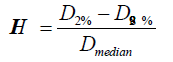

Figure 3: Sample dose colour wash images. Upper left shows acceptable dose coverage of PTVs in left neck from Plan_S for patient 1. Upper right shows acceptable dose to SCM from summation of Plan_F* and Plan_S. Similar results are shown for patient 2 in the lower images.
where Dmedian is the median dose to the PTV, and D2% and D98% are the maximum and minimum doses that cover 2% and 98% volume, respectively, of the PTV on the dose volume histogram [12-14].
Quality Assurance: Patient-specific QA were performed with an in-house program, Epidose [15]. Epidose uses portal images (without the patient) to reconstruct the 3D dose distribution in a cylindrical phantom. This can then be compared to the dose distribution generated by the treatment planning system.
Results
The cumulative doses to critical structures from the summation of Plan_F* and Plan_S and dose to PTVs and HI from Plan_S are summarized in Table 3.
Plan_F and Plan_S for all patients passed verification with at least 90% of points in agreement between the Epidose and the treatment planning system (TPS) dose distributions in the phantom. Our standard passing criteria for IMRT plans is a dose tolerance of +/- 3% and a position tolerance of 3mm.
Discussion
81.84% of PTVLS1 was covered by 100% of the prescribed dose. Since PTVLS1 was a complex target spanning the entire left neck, this degree of coverage was deemed acceptable by the RO. The volume receiving more than 115% of the prescription was less than 0.1 cm3 for both patient 2 and patient 3.
Various approaches have been taken to account for previous irradiation. Some centres assume that irradiated CNS tissues will recover by 50% of the dose received if there is an interval of more than one year from the initial treatment [9,12]. Other centres assume no recovery and simply add the physical doses of the initial and subsequent treatment courses when considering tissue tolerances [11]. It is also possible to use the MIM® (MIM Software Inc.) biological model to calculate the biological equivalent dose delivered to structures of interest [16].
At our centre, we have adopted dose constraints outlined in the National Cancer Institute of Canada Clinical Trials Group HN 6 protocol [13]. Dose constraints for the SCM and BSM were limited to 52 Gy and 60 Gy respectively. If such doses were delivered to these structures from first-irradiation and one assumed that the spinal cord and brainstem recovered by 50% of the dose, the dose constraints for second-irradiation would be 26 Gy and 30 Gy respectively. Although such constraints could be met in some cases, they would not be met in other situations and there remains uncertainty about the validity and amount of dose recovery. For these reasons, we felt that it would be better to have a technique that does not rely on somewhat arbitrary assumptions of dose recovery.
FMBP-IMRT involves accounting for the cumulative SCM dose from both treatments while removing dose from the firstirradiation to the new second-irradiation PTV. Unfortunately, the planning system does not allow the dose map to be edited in such a way. Our solution is to delete the fluence outside of SCBM, recalculate the dose with the modified fluence on the secondirradiation planning CT and use this as the base plan (Plan_F**).
In the majority of cases, the dual goals of retaining the SCBM dose while deleting the dose to new PTV region are met with FMBP-IMRT. However, in some cases, the fluence from SCBM will make a significant dose contribution to the new PTV. We have addressed this issue by dividing the PTVHS and PTVLS into volumes where the dose is above (designated as “PTV_above mean”) and below (“PTV_below mean”) the mean dose in the respective target volumes. When performing Plan_S optimization, different constraints were used for PTVS_above mean and PTVS_below mean. For example, if Plan_F** delivered a mean dose of 10 Gy to PTVHS and the goal of second-irradiation was to deliver 60 Gy to PTVHS, Plan_S would be optimized with Plan_F** as base plan to deliver a “cumulative” dose of 70 Gy to PTV_above mean.
To demonstrate the advantage of FMBP-IMRT, we also generated Plan_S without using a base plan and using Plan_F* without dose modification as base plan. In both cases, the aim was for 95% of PTVHS to be covered by 100% of the prescription.
Without using a base plan, the precise location of the Dmax (SCM) would be unknown so one would need to assume that all parts of the cord received this dose (Table 4). This SCM sparing priority approach would further limit the ability to deliver dose to the new PTV since the distances from PTVLS to the SCM are short. As the rule of thumb, the maximum dose fall-off gradient (MDFO) of an IMRT plan should be less than 7% per millimetre; otherwise, PTV coverage tends to be compromised or the global maximum dose will be higher.
If one limits the cumulative dose to SCM to 52Gy from the sum of the first and second irradiation plans, the best achieved D95% of PTVHS from the second irradiation plan would too low for treatment (Table 5) for all patients.
An alternative approach to planning second-irradiation is to cover 95% of PTVHS volume by 100% of the prescribed dose while constraining SCM dose as much as possible. Using this PTV coverage priority approach, the cumulative dose to SCM from the sum of Plan_F* and Plan_S would be unacceptably high for all patients. Table 6 shows the results of this approach.
Another approach for planning second-irradiation is to use Plan_F* directly as a base plan. This unmodified base plan approach would account for the entire dose previously delivered to SCM. Unfortunately, the doses fall off from Plan_F* will have a strong dose influence to the new PTVs preventing a uniform dose distribution for Plan_S. When using the unmodified base plan approach, and constraining the cumulative maximum dose to SCM to less than 52 Gy, the maximum dose in the Plan_S would be too high and the high dose regions (HiDR) receiving more than 115% of the prescription in the treatment region would be too large (Table 7).
The selection of the margin used for SCBM was made after several analyses. If no margin was used on SCM and BSM, the dose to these structures would be underestimated because the effects of scatter would be ignored. Conversely, if too large of a margin was used, this would be similar to the unmodified base plan approach. We generated Plan_F** with 0.5 cm, 1.0 cm and 1.5 cm margins on CNS to examine the differences. Taking the global maximum dose, HI value and maximum dose to CNS into consideration, the margin of 1.0 cm was found to be the optimal choice.
FMBP-IMRT has since been adopted as our standard secondirradiation planning technique. One caveat is that FMBP-IMRT cannot be used when VMAT was used for first-irradiation because the TPS does not provide a fluence map. As a consequence, our centre will only use IMRT for first-irradiation when the target volume is unilateral. Although FMBP-IMRT was designed for unilateral situation, it can also be used on non-unilateral cases as shown in patient 3. FMBP-IMRT can be used in any situation where one wishes to eliminate the effects of first-irradiation on a new PTV.
Conclusion
We have developed fluence modified base plan for IMRT planning technique for second-irradiation. After the first-irradiation plan is recalculated on the new CT scan, the fluence outside of the spinal cord and brainstem with a 1.0 cm margin is removed. This fluence modified plan is used as a base plan for the development of a second-irradiation plan. This strategy allows us to account for the cumulative dose delivered to the spinal cord and brainstem while allowing coverage of new target volumes.
Conflicts of Interest
The authors declare no conflict of interest.
Funding
No funding support was provided for this study.
References
- Chen A, Farwell D, Luu Q, Cheng S, Donald PJ, et al. (2011) Prospective trial of high-dose re-irradiation using daily image guidance with intensity-modulated radiotherapy for recurrent and second primary head-and-neck cancer. Int J RadiatOncolBiolPhys80: 669-676.
- Chen A, Phillips T, Lee A (2011) Practical considerations in the re-irradiation of recurrent and second primary head-and-neck cancer: who, why, how, and how much Int J RadiatOncolBiolPhys81: 1211-1219.
- Goodwin WJ (2000) Salvage surgery for patients with recurrent squamous cell carcinoma of the upper aerodigestive tract: When do the ends justify the means Laryngoscope 110: 1-18.
- Kao J, Garofalo M, Milano M, Chmura SJ, Citron JR, et al. (2003)Re-irradiation of recurrent and second primary head and neck malignancies: a comprehensive review. Cancer Treatment Reviews 29: 21-30.
- De Crevoisier R, Domenge C, Wibault P, Wibault P, Koscielny S,et al. (1998)Full-dose re-irradiation for unresectable head and neck carcinoma: Experience at the Gustave-Roussy Institute in a series of 169 patients.J ClinOncol16:3556–3562.
- Spencer SA, Harris J, Wheeler RH, Machtay M, Schultz C,et al. (2008) Final report of RTOG 96-10, a multi-institutional trial of re-irradiation and chemotherapy for unresectable recurrent squamous cell carcinoma of the head and neck. Head and Neck30:281–288.
- Lee N, Xia P, Quivey JM, Sultanem K, Poon I, et al. (2002) Intensity-modulated radiotherapy in the treatment of nasopharyngeal carcinoma: An update of the UCSF experience. Int J RadiatOncolBiolPhys53:12–22.
- Koutcher L, Lee N, Zelefsky M, Chan K, Cohen G, et al. (2010) Re-irradiation of locally recurrent nasopharynx cancer with external beam radiotherapy with or without brachytherapy.Int J RadiatOncolBiolPhys76:130-137.
- Sulman EP, Schwartz DL, Le TT, Ang KK, Morrison WH, et al. (2009)IMRT re-irradiation of head and neck cancer- disease control and morbidity outcomes. Int J RadiatOncolBiolPhys73:399–409.
- Lee N, Chan K, Bekelman JE, Zhung J, Mechalakos J, et al. (2007)Salvage re-irradiation for recurrent head and neck cancer. Int J RadiatBiolOncolPhysiol68:731–740.
- Zwicker F, Roeder F, Hauswald H,Thieke C, Timke C, et al. (2011) Re-irradiation with intensity-modulated radiotherapy in recurrent head and neck cancer. Wiley Online Library. 33:1695-1702.
- Ang KK, Jiang GL, Feng Y, Stephens LC, Tucker SL, et al. (2001)Extent and kinetics of recovery of occult spinal cord injury. Int J RadiatOncolBiolPhys50: 1013–1020.
- Siu L, Waldron J (2008) A phase III study of standard fractionationradiotherapywith concurrent high-dose cisplatin versus acceleratedfractionationradiotherapywithpanitumumab in patients withlocallyadvanced stage III and IV squamouscellcarcinoma of the head and neck. National Cancer Institute of Canada Clinical Trials Group (NCIC CTG), NCIC CTG Trial: HN.6.
- Shaw E, Kline R, Gillin M, Souhami L, Hirschfeld A, et al. (1993) Radiation therapy oncology group: Radiosurgery quality assurance guidelines. Int J RadiatOncolBiolPhys27:1231-1239.
- AnsbacherW (2006) Three-dimensional portal image-based dose reconstruction in a virtual phantom for rapid evaluation of IMRT plans. Med Phys 33: 3369-3382.
- Jacobs P, Nelson N, Liu I (2007) Biological effective dose and tumor control probability modelling using the MIM® Software Suite. MIM Software Inc. white papers.

Open Access Journals
- Aquaculture & Veterinary Science
- Chemistry & Chemical Sciences
- Clinical Sciences
- Engineering
- General Science
- Genetics & Molecular Biology
- Health Care & Nursing
- Immunology & Microbiology
- Materials Science
- Mathematics & Physics
- Medical Sciences
- Neurology & Psychiatry
- Oncology & Cancer Science
- Pharmaceutical Sciences