The Structural Shielding of the New Radiotherapy Bunker at the General Hospital of Yaounde in Cameroon: An Enhancement of Radiation Protection
Tetchoka Manemo Cedric, Samba Ngano Odette, Alain Jerve Fotue, Chi Emmanuel and Lukong Cornelius Fai
Tetchoka Manemo Cedric*,Samba Ngano Odette*, Alain Jerve Fotue, Chi Emmanuel and Lukong Cornelius Fai
Department of Physics, Electronics and Signal Processing Research Unit, University of Dschang, Dschang, Cameroon
- *Corresponding Author:
- Tetchoka Manemo Cedric
Department of Physics,
Electronics and Signal Processing Research Unit,
University of Dschang,
Dschang, Cameroon,
Tel: 676394161;
E-mail: tetchoka2010@yahoo.com - Samba Ngano Odette
Department of Physics,
Electronics and Signal Processing Research Unit,
University of Dschang P.O.Box 67 Dschang,
Cameroon,
Tel: 675389140;
E-mail: nosambacm@yahoo.fr
Received Date: November 12, 2020; Accepted Date: November 27, 2020; Published Date: December 04, 2020
Citation: Cedric TM, Odette SN, Fotue AJ, Emmanuel C, Fai LC (2020) The Structural Shielding of the New Radiotherapy Bunker at the General Hospital of Yaounde in Cameroon: An Enhancement of Radiation Protection. Dual Diagn Open Acc Vol.5 No.3:13.
Abstract
The purpose of the this work is the assessment of the new radiotherapy bunker and structural shielding to better enhance radioprotection and reducing the rate of mortality of cancer patients at the General Hospital of Yaoundé (GHY) Cameroon. We used data from the Cobalt-60 machine (60Co), Linear Accelerator (LINAC) and measurements done on the new radiotherapy bunker. From our results and analyses, with the Tenth Value Layer (TVL) for 90° scattered radiation, doors with 6.5 mm thickness of lead would reduce the weekly dose as follows: From 490 μSv·week–1 to around 49 μSv·week–1 case of 60Co; From 435 μSv·week–1 to around 43 μSv·week–1 case of 6 MeV Linac; From 289 μSv·week–1 to around 28 μSv·week–1 case of 18 MeV Linac, which are well within the design dose limit (120 μSv·week–1, 6 mSv/a) very acceptable.
Keywords
Radiotherapy bunker; Shielding calculations; Radiation safety
Introduction
Structural shielding design in medical radiotherapy installations aims to limit radiation exposures to members of the public and employees to an acceptable level, that is: to reduce the effective dose from a Linear Accelerator (LINAC) and Cobalt-60 machine (60Co) to a point outside the radiotherapy bunker as low as reasonably achievable. Shielding design is particularly concerned with attenuation of the primary beam and secondary radiation in the form of head leakage, patient and wall scatter. Thus, finding the optimum barrier thickness is an essential requirement for the safety of radiotherapy facilities [1]. About half of all cancer patients receive radiotherapy, either as part of their primary treatment or in connection with recurrences or palliation f2]. Recommendations and technical information for the shielding design and evaluation in modern radiotherapy facilities, using megavoltage x-ray and gamma-ray, are fully described in Report No. 151 of the National Council on Radiation Protection and Measurements (NCRP) [2]. NCRP 151 is one of the most suitable documents to estimate shielding requirements in medical installations using linear accelerators [1].
The objective of this work is to assess and structurally shield the new bunker at the GHY as prescribed in Appendix IV of the International Basic Safety Standards for Protection against Ionizing Radiation and for the Safety of personels, Safety Series No. 115 (BSS) [2]. This paper’s methodology is intended to be used primarily by health physicists, medical physicists and other radiation protection professionals in structural design shielding of new radiotherapy facilities and in the remodeling of existing facilities. It draws together information from several works with regard to the requirements of the BSS [3,4] it provides guidance on the design of radiotherapy facilities and describes how the required structural shielding should be determined. In the United Kingdom, a design dose limit of 6 mSv/a is used for controlled area [5]. In some hospitals for instance in the USA, radiation safety regulations specify a TADR (Rh) limit of 20 μSv per hour in public places if no special procedure is to be performed, then the dose will be distributed evenly throughout the year and the weekly dose limit be (6 ⸓ 50)=0.12 mSv per week for public areas, the limit is 0.3 mSv/a or (0.3 ÷ 50)=6 μSv per week. It is based on this designed dose limits that we decided to carry out this practical work in Cameroon. The design of radiotherapy facilities so that security objectives for radioactive sources can be met is addressed in this paper to ensure radiation safety of workers and surrounding inhabitants.
Materials and Methods
The calculation methods to evaluate barrier thicknesses were carried out for a treatment room with VARIAN linac (6 MV and 18 MV), maximum nominal energy and 3D-CRT. The LINAC isocenter located at 1 m from the radiation source and assumed a symmetric distribution of gantry treatment angles as well as 60Co machine. It was used, in this study, the TVL values recommended in each norm: NCRP and DIN, for the same shielding material, the ordinary concrete. For both cases, was used the same weekly workload (W). In terms of use factor (U), occupancy factor (T) and shielding design goals (P), for workers and public members. We equally used measuring tapes, rulers, protractors stop watches to carry out essential measurements.
Shielding calculation strategy
The design philosophy for the radiation barriers will depend on the legal dose limits in force. At the present time the BSS prescribe the dose limits. Government bodies have incorporated these standards in legislation. The dose limits set by the BSS, the USA [6], NCRP [5,7] and the United Kingdom [8] relevant to barrier design for radiation treatment units are summarized in Table 1. The scheme used to calculate the barrier thickness for norms include:
| Dose limit | IAEA | USA | United Kingdom |
|---|---|---|---|
| Occupational exposure dose limit | 20 mSv per year averaged over 5 consecutive years and 50 mSv in any single year | Implied annual limit of 10 mSv, cumulative dose of age × 10 mSv and 50 mSv in any single year | 20 mSv in a year or 100 mSv in 5 consecutive years and 50 mSv in any single year |
| Design dose limit for occupational exposure | Fraction of 10 mSv annually | 6 mSv in a year | |
| IDR is 7.5 μSv·h-1 | |||
| Public dose limit | 1 mSv in a year | Infrequently, 5 mSv annually and continually, 1 mSv annually | 1 mSv in a year |
| Design dose limit for public area | 1 mSv annually 20 μSv in any hour |
0.3 mSv in any year IDR is <7.5 μSv·h-1 TADR is <0.5 μSv·h-1 TADR2000 <0.15 μSv·h-1 |
Table 1 : Summary of recommended/legal effective dose limits and design effective dose limits.
Establish the geometrical features of the reference point;
Identify all types of radiation involved in the calculation;
The barrier thickness calculation based on TVL concept;
The Time Averaged Dose-Equivalent Rates (TADR). TADR is the barrier attenuated dose-equivalent rate averaged over a specified time or period of accelerator operation.
The periods of operation frequently used in radiation protection are the week and the hour. For controlled areas, it is used the weekly time averaged dose-equivalent rate, where its maximum value is equal to shielding design goal (Sv/week), and for uncontrolled areas, the dose equivalent from external sources should not exceed 20 × 10−6 Svin-any-one-hour.
BSS No 47 and NCRP 151 thickness calculation methodologies
Primary barriers: According to NCRP and BSS, the primary barrier thickness can be estimated by the following formula:
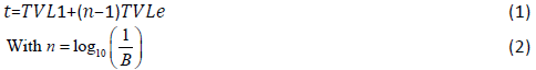
Where t is the barrier thickness;TVL1 and TVLe are the first and equilibrium tenth-value layers, respectively; n is the number of TVLs required for the shield; and B is the attenuation factor of the barrier that will reduce the radiation field to an acceptable level.
For primary beam TVL value is function of the energy of the radiation beam and the type of shielding material, and its attenuation factor (Bpri) is given by:
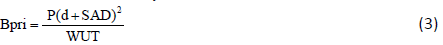
where P is the shielding design goal 0.30 m beyond the barrier (Sv/week);dpri is the distance from the x-ray target to the point protected (m); W is the weekly workload at the reference distance of 1 m (Gy/week);U is the use factor; and T is the occupancy factor.
For leakage radiation, as well as primary barrier, the TVL values depending on the energy of the accelerator and type of shielding material. Its attenuation factor (BL) is given by the following equation:
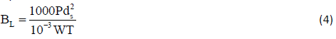
Where ds is the distance from the isocenter to the point protected (m);W is the workload for leakage radiation at the reference distance of 1 m (Gy/week); and the factor 10−3 arises from the assumption that leakage radiation is 0.1% of the useful beam.
For scattered radiation, the TVL values beside of shielding material also are a function of the linac energy and radiation scatter angle. Its attenuation factor (Bp) is given by the following equation:
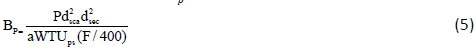
where dsca is the distance from the x-ray target to the patient or scattering surface (m); dsca is the distance from the scattering object to the point protected (m); a is the scatter fraction; Ups is the use factor for patient scattered radiation; F is the field area at mind-depth of the patient at 1 m (cm2); and the factor 400 assumes the scatter fractions are normalized to those measured for 20 cm × 20 cm field size.
Secondary barriers:
Leakage radiation: For a linear accelerator, national and international protocols state that the leakage from the treatment head must not exceed 0.5% of the primary beam, outside the useful beam at 1 m from the path of the electrons between the gun and target window and averaged over 100 cm2. In the plane of the patient, the leakage must not exceed an average of 0.1% and a maximum of 0.2% over a 2 m radius measured from the beam central axis [9]. In general, manufacturers have protected their machines to better than 0.1%, and it would be reasonable to assume this value when determining the required secondary barrier thickness. Based on the NCRP, the required attenuation (BL) to shield against leakage radiation is as follows

Note that in determining protection against leakage radiation, the use factor (U) is always equal to unity and therefore does not appear in the equation.
Scattered radiation: The required barrier transmission (Bp) needed to shield against radiation scattered by the patient is given in equation (7)

The scatter primary ratio’a’ depends on the energy of the X-ray beam and the scattering angle. These data are tabulated per 400 cm2 of irradiated field area for 60Co, 6, 10, 18 and 24 MeV X ray beams in Table 2 [10].
| Angles (degrees) |
Co-60a | 6 MVb | 10 MVb | 18 MVb | 24 MVb | ||||
|---|---|---|---|---|---|---|---|---|---|
| Max a | a at 1.5 cm | Max a | a at 2.5 cm | Max a | a at 2.5 cm | Max a | a at 2.5 cm | ||
| 10 | 1.1 × 10⁻² | 1.68 × 10⁻² | 1.04 × 10⁻² | 1.69 × 10⁻² | 1.66 × 10⁻² | 2.43 × 10⁻² | 1.42 × 10⁻² | 2.74 × 10⁻² | 1.78 × 10⁻² |
| 20 | 8.0 × 10⁻² | 1.15 × 10⁻² | 6.73 × 10⁻³ | 1.03 × 10⁻² | 5.79 × 10⁻³ | 1.17 × 10⁻² | 5.39 × 10⁻³ | 1.27 × 10⁻² | 6.32 × 10⁻³ |
| 30 | 6.0 × 10⁻³ | 5.36 × 10⁻³ | 2.77 × 10⁻³ | 6.73 × 10⁻³ | 3.18 × 10⁻³ | 7.13 × 10⁻³ | 2.53 × 10⁻³ | 7.21 × 10⁻³ | 2.74 × 10⁻³ |
| 45 | 3.7 × 10- | 2.97 × 10⁻³ | 1.39 × 10⁻³ | 3.25 × 10⁻³ | 1.35 × 10⁻³ | 3.05 × 10⁻³ | 8.64 × 10⁻⁴ | 3.06 × 10⁻³ | 8.30 × 10⁻⁴ |
| 60 | 2.2 × 10⁻³ | 1.74 × 10⁻³ | 8.24 × 10⁻⁴ | 1.84 × 10⁻³ | 7.46 × 10⁻⁴ | 1.42 × 10⁻³ | 4.24 × 10⁻⁴ | 1.37 × 10⁻³ | 3.86 × 10⁻⁴ |
| 90 | 9.1 × 10- | 7.27 × 10⁻⁴ | 4.26 × 10⁻⁴ | 7.14 × 10⁻⁴ | 3.81 × 10⁻⁴ | 3.75 × 10⁻⁴ | 1.89 × 10⁻⁴ | 3.53 × 10⁻⁴ | 1.74 × 10⁻⁴ |
| 135 | 5.4 × 10⁻⁴ | 4.88 × 10⁻⁴ | 3.00 × 10⁻⁴ | 3.70 × 10⁻⁴ | 3.02 × 10⁻⁴ | 2.59 × 10⁻⁴ | 1.24 × 10⁻⁴ | 2.33 × 10⁻⁴ | 1.20 × 10⁻⁴ |
| 150 | 1.5 × 10⁻⁴ | 3.28 × 10⁻⁴ | 2.87 × 10⁻⁴ | 3.16 × 10⁻⁴ | 2.74 × 10⁻⁴ | 2.26 × 10⁻⁴ | 1.20 × 10⁻⁴ | 2.12 × 10⁻⁴ | 1.13 × 10⁻⁴ |
aValue s are measured data in [2].
bComputed data from Monte Carlo simulations. The measured values quoted fall between the computed surface values and at a depth, demonstrating the difficulty of measuring the scatter primary ratio.
Table 2 : Scatter Fractions of Dose a, at 1 m, For a 400 cm2 Incident Beam.
F is the field area incident on the patient, in cm2.
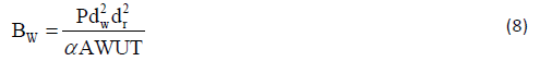
The barrier transmission factor (Bw) needed to shield against scattered radiation when the primary beam strikes a wall is given by the following
Roofs: The roof section that can be struck directly by the radiation beam must be a primary barrier and the formulae used to determine the required thickness are the same as those in Section 2.2.1 (equation (3)-(5)). The design dose limit for the roof will depend on the location of the bunker.
Mazes: A knowledge of the scattering characteristics of X rays (and gamma rays for 60Co sources) by the patient and walls of the room is required when designing a maze or duct. For X ray units operating below 10 MV and 60Co units, the scatter and transmission of primary, leakage and scattered radiation must be considered. For units operating above 10 MV the neutron fluence must be considered. For the equipment arrangement in Figure 1, where the gantry rotation axis is perpendicular to the maze axis, the total dose at the maze entrance Dd will be given by:

Figure 1: Typical room layout where the gantry rotation axis is perpendicular to the maze axis.

Where,  integrates through all gantry angles;
Dp is the dose arising from patient scatter;
f is the primary radiation transmitted through the patient;
Dw is the primary radiation scattered by the wall into the maze;
DLis the leakage radiation scattered down the maze;
DTis the leakage radiation transmitted through the maze wall.
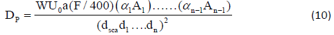
Dose arising from scatter by patient Dp:Figure 2 shows the scatter path along the maze (denoted by the solid lines), with normal incidence on five reflecting walls with 90o reflection from each surface. In practice, it has been demonstrated that the measured dose lies between the answers given by these two methods. In the NCRP [11] formalism, the first scatterer is taken to be the wall but a better approximation is obtained if the patient is taken to be the first scatterer. The dose Dp at the maze entrance due to patient scatter may be determined from equation (10). This equation is valid for any placement of the machine within the treatment room, i.e. the gantry rotation axis either perpendicular or parallel to the maze axis

Figure 2: Schematic diagram to show the scatter paths to the maze entrance.
Dose arising from the primary beam scattered by the wall Dw: When the gantry rotation axis is perpendicular to the maze, the dose Dw will result from the primary beam being scattered from wall H into the maze. In Figure 3, the dose arising from the primary beam scattered by wall H down the maze Dw is given by

Figure 3:Schematic diagram showing the scatter path for the primary radiation beam to the maze entrance (gantry rotation axis perpendicular to the maze axis).

Ar is the cross-sectional area of the inner maze opening, in m
dH is the distance from the radiation source to wall H, in m;
When the gantry rotation axis is parallel to the maze axis the dose DwT will arise from the primary beam transmitted through the maze wall to the maze entrance, as shown in Figure 4.

Figure 4: Schematic diagram showing the scatter path for the primary radiation beam to the maze entrance (gantry rotation axis parallel to the maze axis).
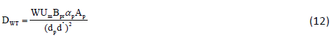
Where; dP is the distance from the source to the centre of wall P;
d” is the distance from the centre of wall P to the maze entrance;
αP is the wall reflection coefficient at P;
AP is the area of maximum field size projected to wall P, in m2
Dose arising from head leakage scatter to the maze entrance DL: The dose at the maze door in Figure 5 due to scattered head leakage DL is given by

Figure 5: Schematic diagram showing the path of scattered head leakage to the maze entrance.
 .
.
Where; L0 is the fraction of the dose due to head leakage at 1.0 m from the radiation source relative to the dose on the beam axis at one meter (this is usually at the isocentre);
As with equation (10), this equation is valid for any machine placement within the treatment room. The fraction of dose due to head leakage is assumed to be 0.001 (0.1%), and the energy of the head leakage radiation may be taken as 1.4 MeV for 6 MV X rays and 1.5 MeV for 10 MV X rays [12].
Head leakage transmission to the maze entrance DT: In Figure 6, the radiation dose at the maze entrance due to head leakage transmitted through the maze wall will be given

Figure 6: Schematic diagram showing the path of head leakage radiation transmitted through the maze wall to maze entrance.
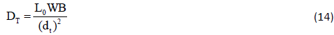
Where; dt is the distance from the radiation source to the maze entrance;
B is the transmission through the maze wall.
This equation is applicable whether the gantry rotation axis is parallel or perpendicular to the maze axis (see equation (10) and (13). Where the maze wall is a primary barrier this contribution should be negligible. There is a special case when the gantry rotation axis is perpendicular to the maze axis, the room has a moderately long maze and the use factor can be assumed as 0.25 for the four major beam directions. The total photon dose at the maze entrance will be the product of 2.64 and the sum of the doses for the worst case scenario. In Figure 3, this will be when the beam is directed at wall H. (Note that the use factor 0.25 should be applied to all four components, including the leakage dose DLH.)

Where; f is the patient transmission factor described earlier in this section and tabulated in Table 3.
| Energy | Co-60 | 6 MV | 10 MV | 15 MV | 18 MV | 25 MV |
| Transmission, f | 0.15 | 0.23 | 0.28 | 0.33 | 0.34 | 0.38 |
Table 3 : Suggested transmission factors (Percentage Depth Doses for a 10 cm × 10 cm field, 100 cm at a depth of 30 cm).
Results and Discussion
60Co Beam facility
Design dose limits: In Cameroon the design dose limit is
Controlled areas=0.12 mSv per week
Public area=6 μSv per week
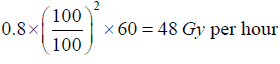
Source specification: If the source specification is 0.8 Gy/min at 1 m and the isocentric distance of the treatment unit (SAD) is 100 cm then the dose raSte at the isocenter is
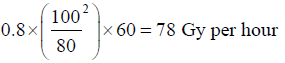
If SAD is rather 80 cm the dose rate at the isocenter is
Work load: For 60Co treatment facility in Cameroon, 20 patients per day (8 hours) is a reasonable assumption for a start. If the dose per patient at the isocenter is 2 Gy and the facility is used five days per week, then the workload is (20 × 2 × 5)=200 Gy per week at the SAD 100 cm.
For a day, it will be 200 Gy ÷ 5=40 Gy
For one hour=40 Gy ÷ 8=5Gy
Primary barrier (B): The required attenuation of the barrier B may be determined according to the following equation:
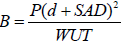
P=0.8 mSv week-1, SAD=1 m, d=3.3 6 m, w=200 × 103 mSv week-1, u=0.25, T=1
We therefore have; B=3.041536 × 10⁻⁴
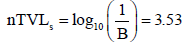
From here we proceed to obtain the thickness of concrete. The thickness of the concrete can how ever be obtained from the attenuation graphs or use of the Tenth Value Layer (TVL) [13], it is obtained according to the following equation
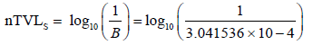
nTVLS= 3.517
The TVL for 60CO in concrete (density) of 2350 Kg.m-3 is 218 mm (Table 4).
Therefore the required thickness barrier is 3.517 × 218=766.69 mm.This is for controlled areas.
Instantaneous dose rate: The barrier thickness required to reduce the IDR to an acceptable level on the far side of the barrier is determined as follows;
The attenuation required BDR is given by:
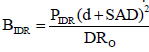
The required thickness is therefore 5.10×218 =1112.mm
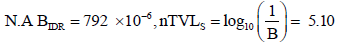
In the GHY, the area beyond the 60Co bunker is an office with a high occupational factor, as such we shall use a design limit of 7.5μSv h-1 for this public area and redo the calculations
Givens; p =7.5 u Svh-1, d = 3.36 m, W = 5 Gy.h-1=5 × 10⁻⁶ μSvh-1, S.A.D = 2.85× 10⁻⁵
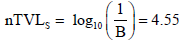
The wall thickness required to reduce the IDR to 7.5μSvh-1 is therefore 4.55 × 2.8 = 490.8 mm. Compared to the initial thickness of 766.69 mm, the later thickness would be required for primary barrier to shield the office.
Secondary barrier: Leakage Radiation-To determine the required barrier thickness (BL) to attenuate the leakage radiations we make use of the following equation:
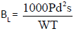
N.B: the use factor here is always equal to unity
Given; P=0.8 msv per week, ds=4.37 m, T=1, W=200 × 103 msvper week
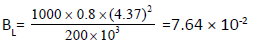
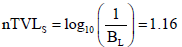
i,e. a wall thickness of 1.16 × 2.8=243.5 mm concrete is required. Scatter Radiation-The barrier necessary to shield against radiation scattered by the patient is determined from the following equation:
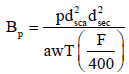
Now: P=0.8 mSvper week, dsca= 1 m, dsec=4.37 m
A: The scatter fraction for 90° scatter is 0.000 g (Table 4) per 400 cm2 of area irradiated.
F is the maximum field area incident on the patient=200 × 150=300 cm2
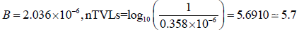
For the 90° scatter; the energy of the scatter radiation will be degraded and the protection designed for leakage radiation should provide adequate protection against radiation scattered from patient.The TVL for the 90° scattered radiation is 151 mm concrete
The wall thickness of ![]() 142.89 mm concrete is required.
142.89 mm concrete is required.
Dose at entrance door-The dose at the entrance door usually comprise the dose scattered by the patient primary beam scattered by the wall, leakage radiation scattered down the maze and leakage radiation transmitted through the maze wall.
The dose scattered by patient Dp is given by equation:
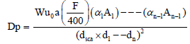
Now given w: 200 Gy per week
a for 90° scatter coefficient at the wall for 0.5Mev is 0.021 for 45° incidence and 15° reflection (value rounded from Table 4) is 7.30 m (w) × 4.01 m (H)=29.3 m2
dsca is 1 m, d1=6.0 m, d2=7.84 m
Dp=4.33 × 10⁻⁵ Gy per week
The dose scattered by the wall to the entrance Dw is determined from the following equation
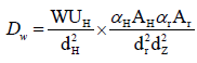
Dw = 3.63 ×10⁻⁶Gy per week
The leakage scattered down the maze DL is determined from the following equation:
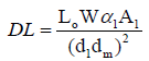
Given; LO = 0.001, α1=1.07 × 10⁻² for 45° incidence and 15° reflection for 60Co (Table 4)
A1=29.3 m2,dm = 7.84 m, d1=6.00 m
DL=2.83 × 10⁻⁵ Gy per week
The dose at the maze entrance arising from leakage transmitted through the maze wall DT is given the following equation.

Where, B is the transmission factor through the maze,
dt is the distance from the radiation source to maze entrance
Now given, B =1.06 × 10⁻⁴, LO=0.001, d =6.7 m
DT =4.72 × 10⁻⁵ Gy per week
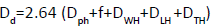
The total dose at the door Dd for the worst case when the beam is directed at wall B is obtained by using the equation below
Dd=2.64(DpH+f × DWH+DLH+DTH)
Where f is the patient transmission factor described earlier in this section and tabulated in Table 3.
f=0.15 for 60Co
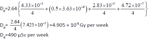
The first, third and fourth terms are each divided by 4 since it is assumed that the gantry will only be in this orientation for 0.25 of the total use. The second term, which arises from the primary beam scattered by the wall, will usually be attenuated by the patient before it strikes the wall, but a transmission factor of 1.0 has been used. Since this is the dose for the, worst case the total dose per week will be less than four times this amount.
Since the area immediately outside the doors is a controlled area, then the dose limit is 120 μSv·week–1 (6 mSv/a). To reduce the dose to an acceptable level, one TVL would be adequate. The radiation scattered by the patient, the primary beam scattered by wall B and the leakage radiation scattered down the maze have all suffered at least one scatter to arrive at the maze entrance, so the TVL for 90° scattered radiation may be used to determine the necessary door thickness. Based on the TVL for 90° scattered radiation, shielding the doors with 6.5 mm thickness of lead would reduce the weekly dose from 490 μSv·week–1 to around 49 μSv·week–1, which is well within the design dose limit and very acceptable.
Furthermore, since the bunker is a single storey building, the only consideration may be the limitation of access to the roof space as such the effect of sky-shine is not considered which may result in the irradiation of nearby buildings. There is no nuclear medicine department nearby, if it were the case, then it should be noted that gamma cameras and possibly other imaging equipment are particularly sensitive to low levels of radiation that can affect certain patient investigations. Next to the bunker is a mortuary hence no effect on corpse. If the building has further floors above the bunker, then consideration should be given to locating a storage room or plant room immediately above the bunker (A plant room is used to house the chiller unit for the linear accelerator or heating and ventilation system plant). A storage room or plant room will have limited occupancy and access can be restricted, thus allowing a greater design dose limit than if an office was placed directly above the bunker.
6 MeV Linear accelerator facilities
The design dose limits to be used are those for public areas 0.3 mSv per year per installation. The IDR should be limited to 7.5 μSv per hour. The expected workload is 20 patients per day (8h), 5 days per week and a dose of 3 Gy delivered at the isocenter per patient.
Similar calculations were meticulously done for the case of a 6 MeV linac based on Figure 7 just as the case case of the 60Co machine and the following results were obtained
From Table 4, the TVL for 6MV X-rays in concrete is 343 mm and as such, the required barrier thickness is (5.7× 343)=1955.2 mm
Therefore, the barrier thickness is=1955 mm
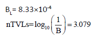

Figure 7: Schematic layout of a 6 MV facility.
From Table 4, TVL in concrete for 6 MV leakage radiation is 279 mm.
Therefore, one secondary barrier should be (3.079 × 279 mm)=859.1 mm ≈ 859 mm.
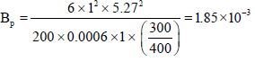
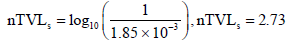
Therefore the required barrier thickness will be 2.73 279=7632.3 mm
Therefore the required barrier thickness will be ≈7632.3 mm
Dose rate at mate entrance
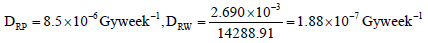 .
.
Therefore DRW=1.88 × 10⁻⁷ Gyweek-1
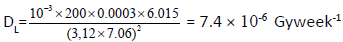 .
.
Dose rate from head leakage transmission to the maze entrance
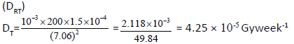
The total dose rate at the door will be the sum of the above dose rates; thus
DRd=2.64/4(8.5×10-6 + 4 × (1.88 ×10-7) + 7.4 × 10⁻⁶ + 4.25 × 10⁻⁵)
DRd= 4.35 × 10⁻⁵ Gy week-1 ≈ 435 μSv week-1
As previously done, shielding the door with a 6.5 mm think of lead reduces this dose to approximately 43 μSv week-1 which is acceptable and less than the normal 120 μSv week-1.
18 MeV Linear accelerator facilities
The Figure 8 below shows a proposal for an 18 Mv linac facility located in the USA. The design does limits to be used are 1 mSvper year per installation for public areasand 5msv per year for the treatment controlled area [13]. The dose in any hour limit (Rh) is 20 Sv. The expected work is 40 patients per 8 hour day, 5 days per week and a dose of 3 Gy delivered at the isocenter per patient. The accelerator has a maximum dose output rate of 12 Gymin-1 and the normal rate used is 5 Gymin-1. We proceeded in a similar manner to get the following results.
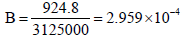

Figure 8:Schematic layout of an 18 MV facility.
The required number of TVLs to produce this attenuation is determined from equation (2)
The TVL for 18 mv x-rays in concrete is 445 mm (Table 4) and therefore the required barrier thickness is (3.53 × 445)=1570 mm
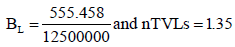
The required attenuation barrier will therefore be (1.35× 445) =602 mm.The number of TVLs to shield against leakage is much lower than the number required for primary beam shielding. Therefore, the leakage shielding requirement is more than adequately met by the primary barrier thickness
The required TVL to produce this attenuation is determined from equation (2) n=2.38
The TVL for 18 mv x-ray in concrete is 445 mm (Table 4) and therefore the required barrier thickness is (2.38 × 445)=1058.9=1059 mm
Compared with the number of TVLs required to attenuate the primary beam calculated above, the thickness requirement to attenuate the worst case of patient scatter is more than one TVL lower. Therefore the wall thickness determined for the primary barrier will be more than adequate to shield against scattered radiation. For other gantry angles, the scatter fraction will be much reduced and the energy of the scatter radiation is much lower. Therefore the barriers thickness required to attenuate the primary beam will be sufficient to attenuate all scattered radiation
Treatment control Area
Primary barrier at location D
B=1.85 × 10⁻⁵ and nTVLs=4.73
The required thickness is (4.73 × 445) =2106.15 ≈ 2106 mm
Secondary barrier:
Public area at A: Leakage and patient scatter considerations.
Only leakage and patient scatter are considered since there is no primary radiation directed at location A. for conservative reasons, the minimum scatter angle of 30° is used to look up and the scatter fraction a from Table 4. The input data value used in equations (2)-(5)
| Type of area | NCRP 49 | BIR/IPEM 2000 |
|---|---|---|
| Offices, reception areas, laboratories, shops, children’s play areas, nurse’s stations, staff rooms, control rooms | 1 | 1 |
| Wards, patient rooms | 1 | 0.2 |
| Patient examination and treatment rooms | - | 0.5 |
| Corridors | 1/4 | 0.2 |
| Toilets, bathrooms, outside areas with seating | 1/16 | 0.1 |
| Stairways, unattended waiting rooms, store rooms (not film) | 1/16 | 0.05 |
Table 4 : Different Suggested Occupancy Factors (t).
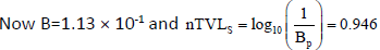
BL=5.38 × 10⁻³
For patient scatter, equation (4) is used given;
BP =2.84 × 10⁻³
Maze door area: For a high energy accelerator, the contribution of leakage and scatter radiation reaching the maze door is relatively low while the capture gamma and neutrons dose components
The dose at the door Dd is given by
Where each component is calculated as follows
Patient scatter component DPH
Equation (5) is used to determine the dose at the door scattered by the patient with the beam pointing at the wall H, or location c, as shown. The input data are
DP =3.26× 10⁻⁵ Gyweek-1
Wall scatter component DWH
DwH=1.24× 10⁻⁷Gyweek-1
Head leakage wall scatter component DLH
DLH =1.02× 10⁻⁵Gyweek-1
Head leakage through the maze wall DTH
DT=6.02× Gy-7Gyweek-1
The total dose rate at the door will be the sum of the above dose rates; thus
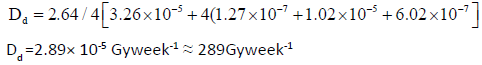
As previously done, shielding the door with a 6.5 mm think of lead reduces this dose to approximately 28 Gyweek-1which is acceptable and less than the normal 120 Gyweek-1.
Conclusion
Radiotherapy and radioprotection today remains the one of the best available strategy in the fight towards reducing the rate of mortality and morbidity. This study was designed to evaluate the level of radiotherapy facilities in the GHY and compare to the norms prescribed by international organizations.
From our results we can conclude that:
The structural design and shielding of the new radiotherapy bunker at the GHY are in accordance with the norms of international organizations after using a 6.5 mm thick of lead to attenuate the radiations. This has greatly enhanced radioprotection and guarantees safety of workers and neighboring inhabitants.
After several calculations, the total dose at the maze doors for the 60Co facility, 6 MeV linac facilities and 18 MeV linac facilities were respectively 49μSv week1, 43μSv week1 and 28μSv week1. These values were within the acceptable dose limits of 120μSv week-1, provided a 6.5 mm thick of lead is used to shield the doors.
Cancer treatment centers are still very few in Cameroon since only Yaoundé and Douala have had presumed standard centers.
Rate of mortality and morbidity will continue to be in a rise if radiotherapy facilities are not further improved.
References
- NCRP Report No.151 (2005) Structural shielding design and evaluation for megavoltage x-and gamma-ray radiotherapy facillities, National Council on Radiation Protection and Measurement.
- Food and agriculture organization of the United Nations (1996) International labour organisation, oecd nuclear energy agency, pan american health organization, world health organization, International basic safety standards for protection against ionizing radiation and for the safety of radiation sources, Safety Series No. 115, IAEA, Vienna.
- National council on radiation protection and measurements (1976) Structural shielding design and evaluation for medical use of x-rays and gamma-rays of energies up to 10 mev, Rep. 49, NCRP, Washington, DC.
- Institute of physics and engineering in medicine (1997) the design of radiotherapy treatment room facilities, Rep. 75, IPEM, York.
- National council on radiation protection and measurements (1993) Limitation of exposure to ionizing radiation, Rep. 116, NCRP, Bethesda, MD.
- cool da, peterson ht (1991) nuclear regulatory commission. standards of protection against radiation, 10cfr20, us office of the federal register, Washington, DC.
- International electrotechnical commission (1981) Safety of medical electrical equipment, Part 2: Particular requirements for medical electron accelerators in the eange 1 MeV to 50 MeV, Publication 601-2-1, IEC, Geneva.
- Health and safety executive (1999) Ionising Radiations Regulations, London.
- Health and safety executive (1999) Ionising Radiations Regulations, London.
- International atomic energy agency (2003) Revised categorization of radioactive sources, IAEA-TECDOC-1344, Vienna.
- National council on radiation protection and measurements (1977) Radiation Protection Guidelines for 0.1-100 MeV Particle Accelerator Facilities, Washington, DC.
- Taylor PL, Rodgers JE (1999) Scatter fractions from linear accelerators with X-ray energies from 6 to 24 MV. Med Phys. 26: 1442-446
- Nelson WR, Lariviere PD (1984) Primary and leakage radiation calculations at 6, 10 and 25 MeV. Health Phys. 47: 811-818.

Open Access Journals
- Aquaculture & Veterinary Science
- Chemistry & Chemical Sciences
- Clinical Sciences
- Engineering
- General Science
- Genetics & Molecular Biology
- Health Care & Nursing
- Immunology & Microbiology
- Materials Science
- Mathematics & Physics
- Medical Sciences
- Neurology & Psychiatry
- Oncology & Cancer Science
- Pharmaceutical Sciences